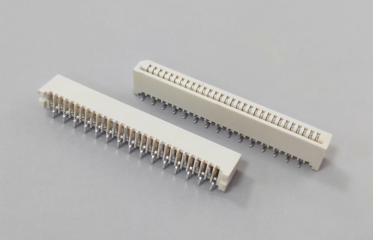
Hello everyone, I am the editor. In almost all electronic and electrical products, board-to-board connectors have become an essential element for connecting various components. The existence of the connector is not only for disassembly and connection, but also a carrier for providing current and signal to the product.
In the process of using connectors, many designers of electronic systems have had a similar experience: using cheap connectors, and then paying a high price, even regret it. Incorrect selection and use of connectors can cause system failures, product recalls, product liability cases, circuit board damage, rework and repairs, which in turn can cause loss of sales and customers. Therefore, when designing electronic products, you must choose a suitable connector for the electronic device. Otherwise, the situation where a small board-to-board connector makes the entire system inoperable will feel very broken.
When people choose a connector, they will first consider cost control. Others are high quality, high stability, and the design features of the connector itself. In order to prevent electronic designers from underestimating the importance of connectors in the design process, due to small losses and big losses, board-to-board connector manufacturers provide some suggestions for everyone:
First: the idea of double pole design. In the ERNI connector series, the double-pole design idea is consistent throughout. Vividly speaking, the double-pole design can be described as “two birds with one stone”. Optimized terminal design to adapt to high-speed signal transmission, providing a higher orientation tolerance. In terms of inductance, capacitance, impedance, etc., the double-bar terminal structure is smaller than the box-type terminal structure for high-speed applications, and optimized to achieve ultra-small discontinuity. The dual-pole design allows multiple connectors to be on one circuit board without plugging or short circuit problems, and there is no need for a large number of signals on a single connector. The simple routing of double poles can save space, make the connector smaller, and simplify the detection of solder pins. For example, put 12 on a board. It also reduces rework costs. Practical applications such as telecommunications terminal user equipment, etc.
Second: Surface mount design with high retention force. For SMT products, it is generally believed that the holding power on the board is poor. Is the PCB retention force of surface mount terminations lower than that of through-hole terminations? The answer is: not necessarily. Design improvements can effectively improve the retention of PCB. If the soldering bracket, the hole (microhole) of the surface mount pin, and the large soldering pad are superimposed, the holding force can be improved. In fact, even I/O connectors can use surface mount pins. This can be vividly compared to “take roots”. For example, in the design of X-ray machines, ultrasonic scanners, and robotic Ethernet switches.
Third: Robust design. To determine the reliability of the connector, while allowing the use of flat crimping tools, the pole plate is fixed on the shell to improve the robustness, to achieve a better manufacturing process and increase output. To sum it up in one word is “solid as a rock.” Specific applications such as positron emission tomography scanners, railway car embedded systems, etc.
Fourth: high current, small spacing design. With the miniaturization of automotive electronics and consumer electronics, the design concept of high current and small spacing needs to be considered.
Fifth: No bent pin design in the assembly process. Traditional stamping will cause bending or deforming of the pins due to improper processing, and the bending process will cause capillary cracks, which is undesirable for the long-term product, and it will also affect the circuit performance and cost. And ERNI uses direct stamping of the corners, stamping terminals can avoid capillary cracks caused by the bending process, and ensure a complete electromechanical connection. The pin coplanarity is 100%, and the tolerance is controlled to ±0.05mm. The 100% surface mount pin coplanarity test ensures the reliability of the circuit board assembly process, ensures good soldering, improves the product quality rate, and reduces the cost. And improve the firmness of the right-angle connector to prevent the connector from being damaged due to improper operation. The term “unbreakable” is very appropriate. It is especially suitable for the InterfaceModule module interface of the inkjet printer controller.
Sixth: Advanced lock design. ERNI uses a double lock design to meet different needs. The positive lock is designed for strong vibration applications. It is very suitable for automotive and subway applications. The friction lock is designed for general vibration applications. Double locks and double safety insurance ensure a reliable connection, and no special tools are required for on-site disassembly (repair/replacement) of cables. Suitable for the design of monitors, LED car lights, etc.
Board-to-board connectors play an important role in the design of the entire electronic system. When selecting electronic components, engineers need to pay attention not only to chip technology, but also to the selection of peripheral components, so as to make the system run smoothly. , Play a multiplier effect.
Post time: Oct-11-2020


